Project overview
For this project I have to design a circuit that will display my date of birth on a single seven-segment display. To do this I have to design a logic circuit made of multiply logic circuits, the logic circuit has 7 inputs and 7 outputs. Then I will have to make a circuit on a breadboard that produce my date of birth.
Truth table
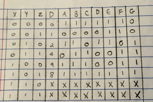
0 represents when the switch is off and 1 to represent when the switch is on. XYZ are the three switches. If the circuit is put to gethher right each combination will display the right digits.
K-Mapping
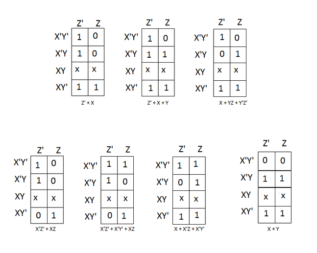
Karnaugh mapping is used to simplify logic expressions using a truth table. The best way to use them is to make the biggest groups as possible. With Boolean algebra simplifying mistakes can occur. With k-mapping its a lot easier and less time consuming.
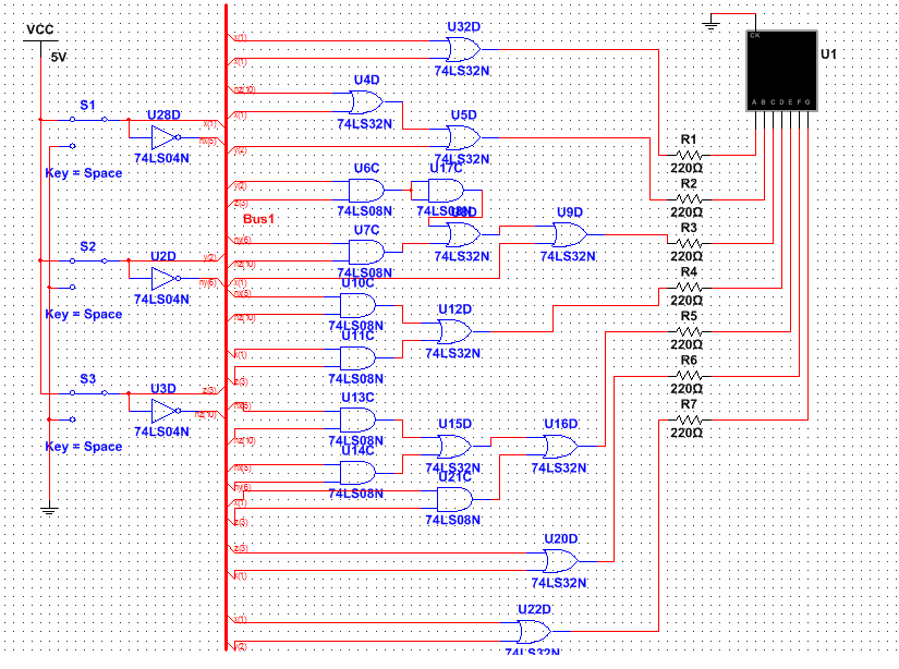
Logic circuit on Multisim
|
For this circuit I used 6 AND Chips, 10 OR Chips, 3 Invert, and 1 NAND chip. My circuit seemed to be more complex than others. Mine was long because I had no repeating numbers in my birth date. Also none of my Letters could be connected straight to ground.
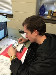
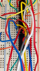
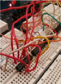
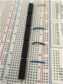
Bread-boarding
|
|
|
|
|
I had to connect the conection on each side of the the 2 channels. Also with this new board the resistors are built in so I didn't have to add them. for my design I used 3 AND Chips, 2 OR Chips, 2 Inverter Chips, and 1 NOR Chip. I had to connect the 5v to power and the ground to negative.
Conclusion
This project was a lot more difficult for me than the Majority Vote was, mostly the bread-boarding part. I had a hard time with the new boards and got confused between chips. Dispite this the K-mapping made it easier. K-mapping is useful because it is a lot faster and less time consuming than using Boolean logic. I like it a lot better than Boolean logic. It's harder to make mistakes using K-mapping, and the mistakes are easier to fix. When 1 is present in the columns, in the truth table, that segment will be lit in the 7 segment display when it is 0, its off. Combinations of the segments that are on will display different numbers.
